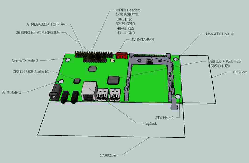
Carrier Board
Features
- Dimensions 17.002 x 8.928cm (Half ITX Motherboard size)
- Gigabit Ethernet RJ45 connector with built-in transformer
- SATA connector
- 5V power plug (5.5mm, 2.1mm centre pin)
- 5V power internal power connector (for SATA or fan)
- 3x USB3.0 connectors
- USB5434-JZX USB3.0 4-port Hub
- 2x USB2.0 Headers
- USB2512BI-AEZG USB2.0 4-port Hub (Tentative)
- 44-pin DIL header with remaining EOMA-68 pins (RGB/TTL, GPIO and I2C)
- ATMEGA32U4 (arduino-compatible bootloader/firmware)
- CP2114 USB Audio IC
- Stereo Headphone jack, Mic-In jack
Note: the provision of USB3 and Gigabit Ethernet is for future compatibility with EOMA-68 CPU Cards that have that functionality.
Pinouts
These are the pinouts for the 44-pin connector:
- Pin 1 GND
- Pin 2 LCD R0
- Pin 3 LCD R1
- Pin 4 LCD R2
- Pin 5 LCD R3
- Pin 6 LCD R4
- Pin 7 LCD R5
- Pin 8 LCD R6
- Pin 9 LCD R7
- Pin 10 LCD G0
- Pin 11 LCD G1
- Pin 12 LCD G2
- Pin 13 LCD G3
- Pin 14 LCD G4
- Pin 15 LCD G5
- Pin 16 LCD G6
- Pin 17 LCD G7
- Pin 18 LCD B0
- Pin 19 LCD B1
- Pin 20 LCD B2
- Pin 21 LCD B3
- Pin 22 LCD B4
- Pin 23 LCD B5
- Pin 24 LCD B6
- Pin 25 LCD B7
- Pin 26 LCD CLK
- Pin 27 LCD VSYNC
- Pin 28 LCD HSYNC
- Pin 29 LCD EN
- Pin 30 I2C-SCL
- Pin 31 I2C-SDA
- Pin 32 GPIO 0
- Pin 33 GPIO 1
- Pin 34 GPIO 2
- Pin 35 GPIO 3
- Pin 36 GPIO 4
- Pin 37 GPIO 5
- Pin 38 GPIO 6
- Pin 39 GPIO 7
- Pin 40 RES1
- Pin 41 UART_TX
- Pin 42 UART_RX
- Pin 43 GND
- Pin 44 +5V
These are the pinouts for the 26 GPIO for the ATMEGA32U4:
- Pin 1
- Pin 2
- Pin 3
- Pin 4
- Pin 5
- Pin 6
- Pin 7
- Pin 8
- Pin 9
- Pin 10
- Pin 11
- Pin 12
- Pin 13
- Pin 14
- Pin 15
- Pin 16
- Pin 17
- Pin 18
- Pin 19
- Pin 20
- Pin 21
- Pin 22
- Pin 23
- Pin 24
- Pin 25
- Pin 26
Feature Requests (already!)
- USB header (10-pin) for connecting in PC cases to front case USB sockets) even if that means adding an extra USB Hub IC. (Added - See Above -C)
- Front Panel audio, power, reset switch and LED headers (shared with GPIO?)
- Power/Reset routed somehow through to the EOMA68 GPIO or some form of power-notification devised (AXP209 PMIC or AXP221 PMIC used?)
- Proper power/reset control of the USB peripherals.
- Shrouded internal power header, 4-pin (e.g. AMP 171825-4) for power-up of the PCB (in addition to the 5V power jack)
- Only put pinholes on the PCB, don't mount DIL headers at factory.
- a provision for either an onboard battery or a header (or pinholes for user mounted header) to connect an external battery to keep the RTC powered separate from internal power header.
- Provisions to power everything off of PoE even if it is just a header (or pinholes for user mounted header) to send the current to a daughterboard voltage regulator that would then supply power back to the internal power header.
- Jumper to disable headphone and Mic-in jacks and enable onboard headers for headphone and Mic-in to route to front case panel or elsewhere
- Use VGA circuit from http://www.gplsquared.com/eoma_boot/eoma_boot.html#vga move the 5V connector to the back, double-stack USB3. Board then becomes a fully-functioning PC with 2 video outputs.
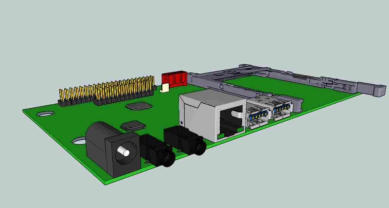
Pictures
These are very early 3D CAD/CAM prototypes, done prior to the PCB layout