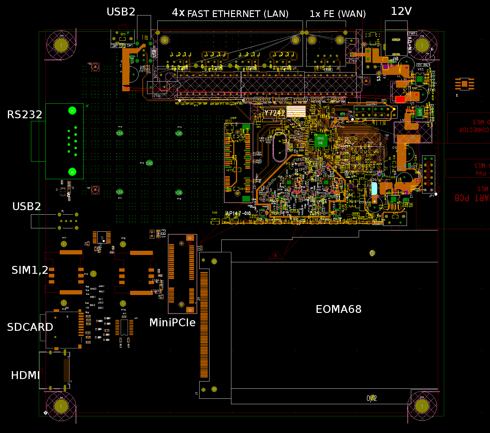
06 May 2017: New design of Router started
The first design of Router was back when EOMA68 had GbE. A decision was taken to remove that, in favour of USB3, which meant that the original Router design had to be re-thought. This design will use a QCA9531 which is an entirely libre-compliance MIPS-based SoC with 2x2 802.11n 2.4ghz WIFI, PCI Express, USB2 and a 5-port Fast Ethernet PHY.
Connectivity to EOMA68 will be handled by an AP2720 USB-to-USB (usbnet) host IC which will appear to both the QCA9531 and EOMA68 as a USB Ethernet device. Also included will be a second (USB-based) MiniPCIe holder where a 3G/4G/LTE USB-based modem can be attached. There will be two SIM card slots so that it is possible to, for example, use one of Telit's world-wide high-availability SIM Cards for telemetry, but if large firmware updates or other high-bandwidth but non-emergency connectivity is required, the second SIM may be utilised with a more "standard" contract.
An HDMI connection is also to be included (with a TFP410A to convert from RGB/TTL to HDMI) as well as a USB2 port to the EOMA68 Card, as well as a 9-pin RS232 port. This will allow KVM access and remote access to the main EOMA68 Card's OS.
Also: the QCA9531 will have the ability to power-cycle the EOMA68 Card, and likewise the EOMA68 Card will have the ability to power-cycle the QCA9531. Through software-level monitoring each device will have the capability to reboot the other. In addition, the EOMA68 SPI interface will be wired through a multiplexer to the QCA9531's SPI NOR Flash. The combination of power-management and control over the SPI NOR will allow a EOMA68 Card to easily re-flash the QCA9531 Operating System, should it become corrupted (unfortunately, the arrangement may not be reciprocated).
Overall this is quite a powerful combination of technology: 5-port Fast Ethernet, 2x2 802.11n 2.4ghz WIFI, MiniPCIe (full MiniPCIe so that 802.11ac or 5.4ghz MiniPCIe Cards may be slotted in), 3G / 4G / LTE or other USB-based MiniPCIe modem and more. VPN encryption may be handled by the EOMA68 Card, which will have a much faster processor than the QCA9531, whilst the QCA9531 itself can remain dedicated to traffic routing and management.
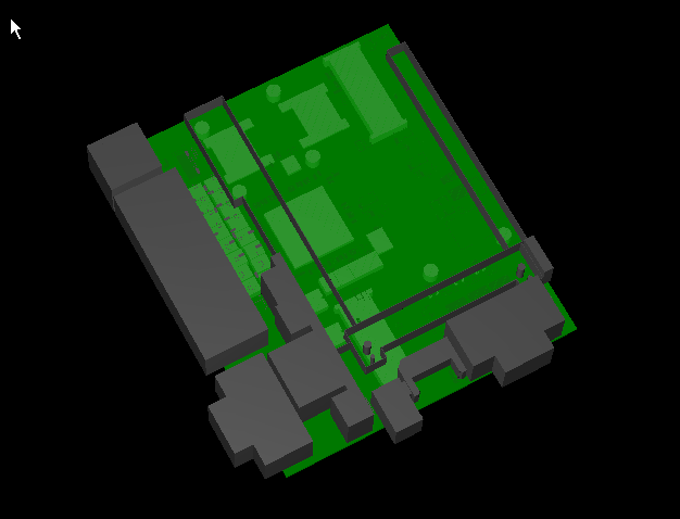
27 Nov 2013: 3D PCB View
Here is a quick 3D PCB Rendering of the EOMA-68 Router. Connectors along the left edge are Dual-USB, 4 Gigabit Ethernet and RS232. Behind those is room for an Ax5300 POE Module. Along the bottom edge is then a 5.5mm Power Jack, SATA and VGA connectors. At the far left edge is an 8-pin Expansion connector with 4 pins GPIO, 5V power and I2C.
On the underside at the top, the USB-based 3G MiniPCIe can be seen, as well as the two SIM sockets. At the bottom, partially obscured by the SATA and EOMA68 is the USB-based WIFI MiniPCIe socket.
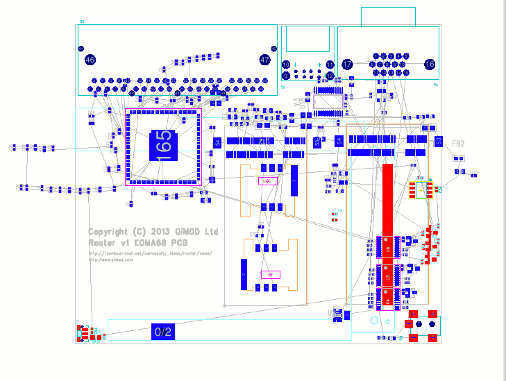
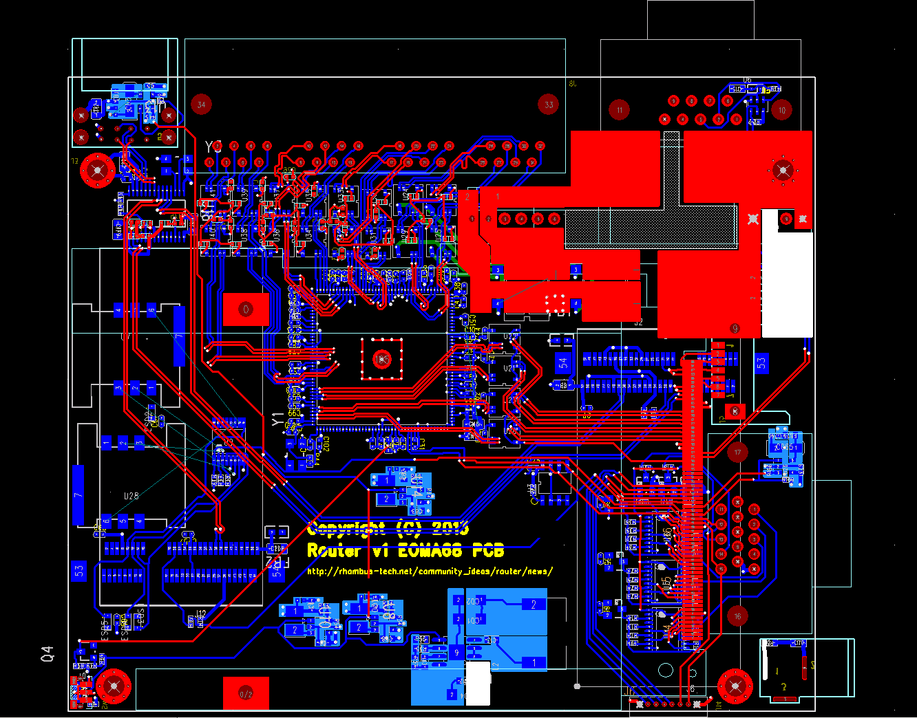
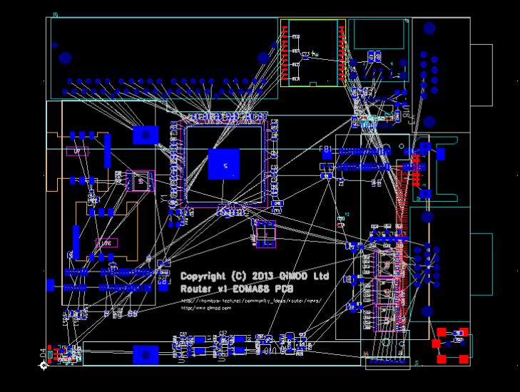
18 Nov 2013: First revision PCB layout progress
Although it is not yet complete this is an almost beautiful design, with a few interestingly-scary areas around the Ethernet connectivity to the 4-port Gigabit RJ45. In the end individual transformers were chosen with centre taps, as the layout could be varied. As there are 5 ethernet ports (one for EOMA68) and there are 4 sets of wires for Gigabit that's 20 transformers! It made for some interesting layout issues given that this is a 4-layer PCB.
Also after talking with people on the list it was decided to add support for POE. The Ag5300 was chosen because it is capable of easily supplying 15W if used in 802.11af mode. Going up to 802.11at (30W) was considered not to be worth sacrificing the pins: there are only 4 GPIO pins left.
Size-wise, the addition of the POE module (60mm long and 18mm wide!) gave some space issues which required a small connector shuffle. USBx2 has moved into the top left corner, along with the USB Power IC and the USB Hub. RS232 moves onto the top edge (right). POE module is just below that, taking up an enormous amount of space due to the size of the heat spreader areas as well as two Bridge Rectifiers. Also added were four mounting holes. USB, 4xGbE and RS232 were all made to "overhang", bringing the unit size to around 11.5cm x 10.3cm with the PCB being slightly smaller. If the overhang of the Power and VGA ports are taken into consideration the unit size is 12cm x 10.3cm.
This PCB layout is, surprisingly, almost ready to go. The placement and layout of the MiniPCIe needs to be double-checked; an alternative SIM slot needs to be chosen; the power plane needs to be done, and that's about it, amazingly.
In essence, this router I/O board covers the options that the Flying Squirrel did not. It can be cut-down (removal of the 4-port GbE) and audio put in its place, and that would make a very good Desktop PC. Perhaps with the addition of an extra 3 or 4 USB ports. Still up for consideration is whether to include an ultra-low-cost PIC or Embedded Controller of some kind. Photo below can be viewed stand-alone (View Image in browser) - it is bigger than shown below, so some of the detail of the connections can be seen clearly.
13 Nov 2013: First revision connector placement
Connector and approximate component placement has been arranged in a double-sided arrangement. This allows the PCB size to be kept to around 115 x 95mm (4.5 x 3.6in) which is around the same size as the Flying Squirrel PCB. Connectors round the top edge (BOTTOM side) are the 4-port Gigabit Ethernet, then a Gigabit Ethernet transformer, then 2x USB2 and RS232. Down the right side (BOTTOM of PCB) is RS232, SATA, VGA and Power. Behind the Power connector is an 8-pin Extension connector which has I2C, 5V, GND and 4 pins of EOMA-68 GPIO. In the centre is the EOMA68 connector (still on BOTTOM) and the Power Switch is in the bottom left corner. On TOP are the two MiniPCIe USB holders for WIFI and 3G USB-based full-sized MiniPCIe cards.
Almost all discrete components are on TOP because there is very little available space on the BOTTOM side due to all the connectors. There actually aren't that many components left to put on: there is the LEDs for the 4-port Ethernet and a 5V regulator to be sourced which can provide enough power for the RTL8366 as well as the EOMA68 CPU Card, as well as power four USB ports. The 4 USB ports are up to 10 watt on their own (!), the RTL8366 is 3 watts and the CPU Card could potentially be up to 4. To be honest a potential total of 20 watts is of some concern!
10 Nov 2013: First revision PCB started
Layout and schematics have begun for the first revision of the EOMA-68 Router I/O Board. This product is an Open Hardware Project and the schematics and PCB design are licensed under the GPLv3+ Software License. Source files and datasheets of components are available here.
This product will use a completely different style from the Flying Squirrel, sticking to dedicated peripheral ICs instead of using an Embedded Controller IC. All on-board peripherals - including the 4-port Gigabit Ethernet IC - will need to be managed by the EOMA68 CPU Card.