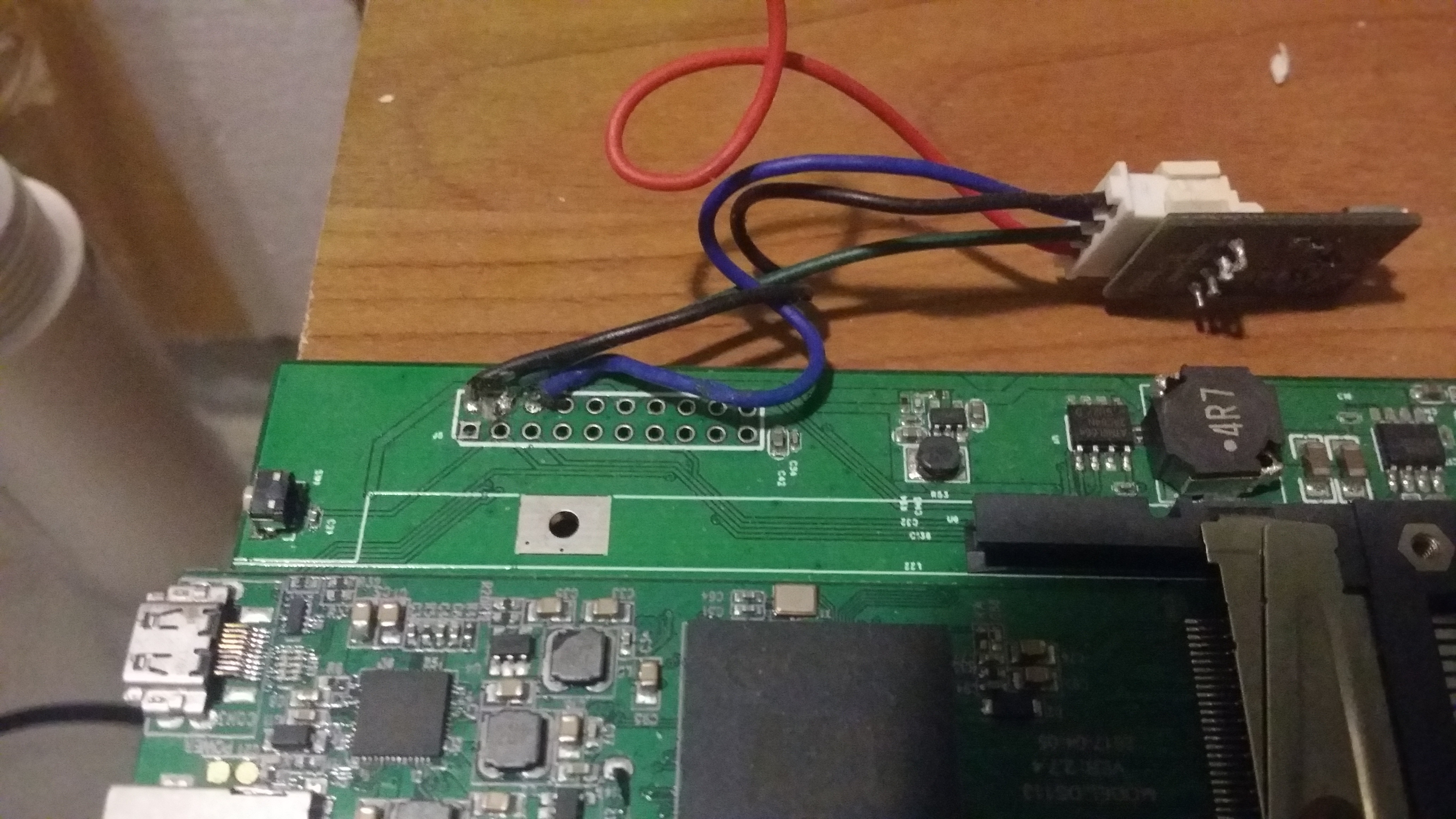
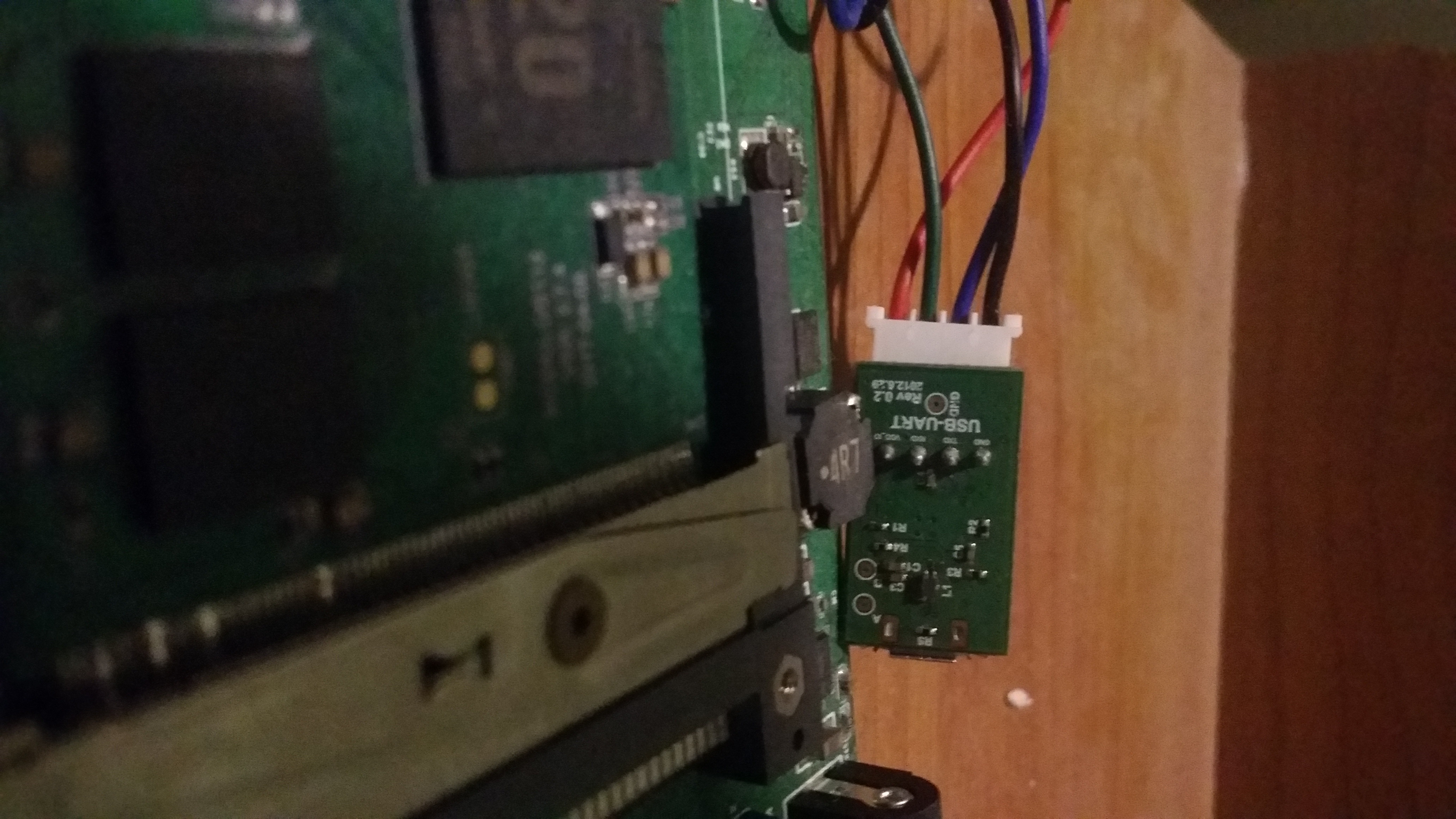
Ok these are the microdesktop with a USBUART attached, you should be able to zoom in and see tx rx on the UART PCB.
You will find quite often that you get a ground loop between the main DC PSU and a laptop's PSU which is often not earthed, over the USB, through the USBUART, to the MD PCB that will, on powerup of the MD, cause the USBUART to either generate random data, or cause it to spike and lock up entirely, or in some cases of extremely cheap FT232 USBUARTs, cause them permanent irrevocable damage.
This is just how it is.
I buy lots of them, and in cases where difficulties occur unplug them before powerup. Of course, uboot needs to then be configured not to autostart too fast, and also you miss the very early uboot-spl debug messages, ho hum.
You need a 5.5mm jack with a 2.1mm centre hole, middle is +ve (aka "pin positive").
Anywhere between 7 and 21v is fine, minimum 1A, 1 5A is better. One of those multi power thingies is fine (5 7.5 9 12v you know the ones I mean, get them at RadioShack... or at least you used to), just make absolutely sure outer is -ve and inner (pin) is +ve.
You almost certainly have a random 12VDC PSU somewhere in the house already, for a toy, a charger, or many 12 VGA monitors use a 5.5mm jack, it's an extremely common standard, can take up to around 4 to 5A no problem.
If you have a multimeter for goodness sake use it.
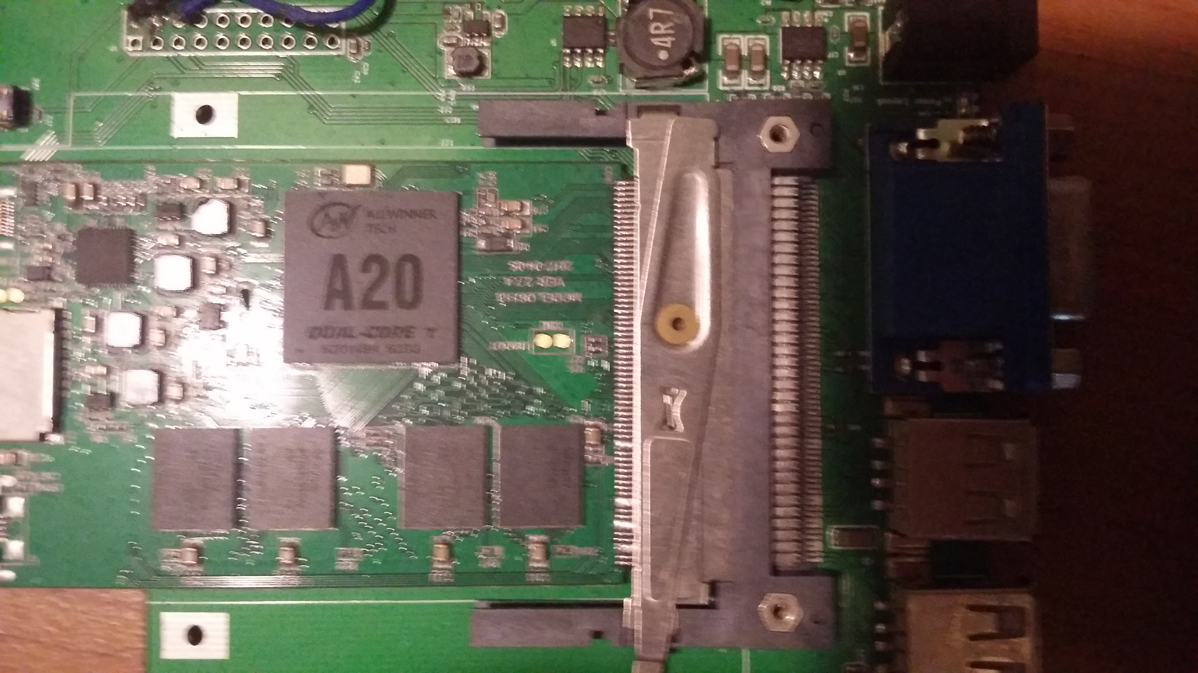
The Card can be powered up whilst attached to USB OTG however although power gets through the PCMCIA connector there is a SY6280 current control IC set at 1A which acts as a diode in this case. You MUST therefore power the PCB from the DC Jack in order for the USBUART to work.
DO NOT wire up the 3.3v supply to the USB UART. ONLY solder on 3 wires: GND TX RX. Those work by sinking current to GND and are otherwise floating, I believe.
However they may be tied to 3.3v pullups actually on the USBUART and I have had this be sufficient in some cases to actually power parts of the A20 processor (!!) even when otherwise fully powered down.