PCBs
PCB1 - Main Board
This is the PCB that takes the EOMA68 CPU Card. It takes USB-OTG-style 5V @ 3A power (which is reversible), contains the LVDS converter IC for the screen, as well as USB connections to the EC board (PCB2), a USB2 Hub and a USB Audio IC (CM108AH).
PCB2 - Embedded Controller Board
This PCB contains an STM32F072, which is permanently powered by PCB1. The STM32F072 monitors power, controls the on/off state of the EOMA68 CPU Card, emulates a keyboard and trackpad as USB devices and much more.
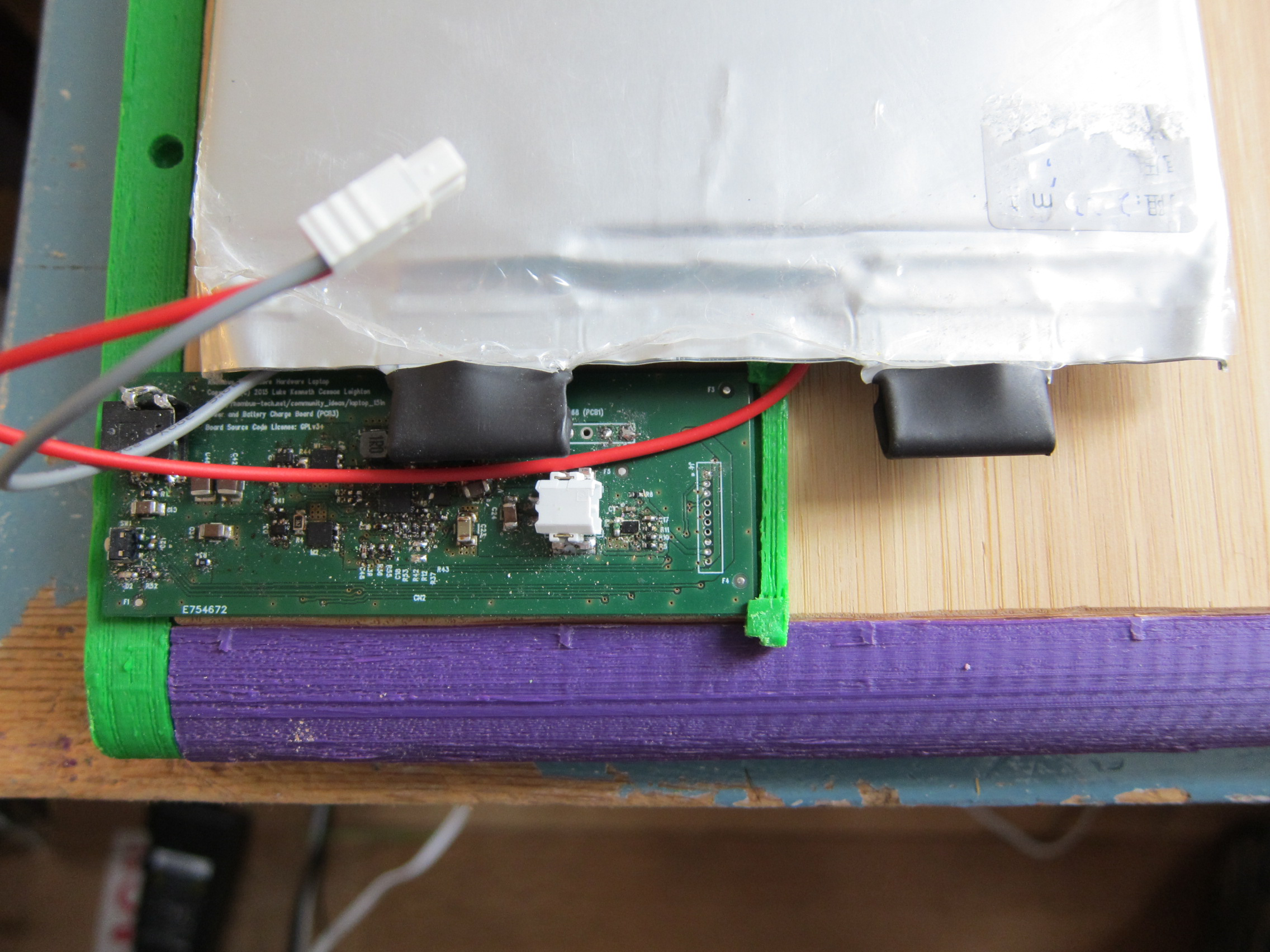
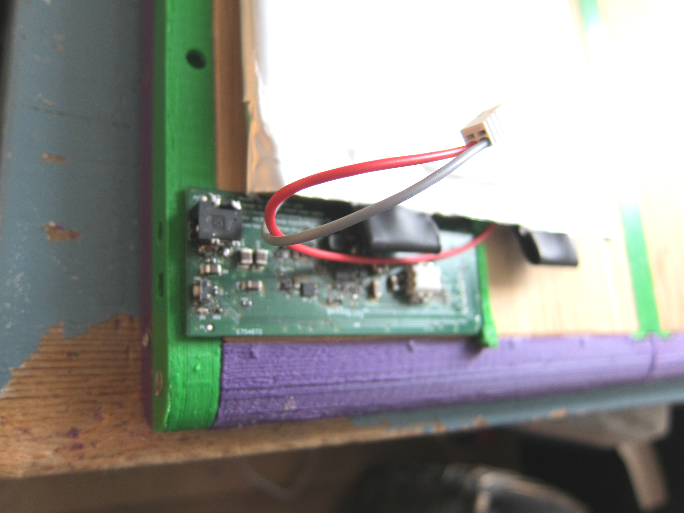
PCB3 - Power Board
This PCB manages the battery, and provides power to both PCB1 and PCB2. It also has a power switch (which is connected directly to the STM32F072 on PCB2 as a "soft switch"). There is also a Battery Charge Monitor (coulomb counter).
Notes:
- PCB3 really does face upside-down, the pictures are taken with the laptop face-down.
- the battery you can see it overlaps the PCB - it's plastic sheath but still, there must be no components on the long side, at least 6mm.
- the PCB doesn't actually slot into the long edge of the casework, but i did leave off any components on the lower long side, as well.
- the off-PCB connectors need to be Right-Angle! the clearance is 6mm, so a vertical SIP Header won't do.
- battery connector should probably be side-to-side (aligned with the long length) just as in the pictures, so that the cables don't have to be bent
- the power button is from ALPS, P/N SKRTLAE10 - it's a right-angle push switch (like the one on LION1CELL01A but only R/A). i can't find EU suppliers but it's extremely common in China.
- the DC jack is CUI INC PJ-018H-SMT - this is easy to get hold of.
Picture of current PCB:
Specification for PCB2-to-PCB3 connector
| Pin Number | Function | Description |
|---|---|---|
| 1 | GND | |
| 2 | SCL | I2C Clock (PCB2 STM32F072 Master) |
| 3 | SDA | I2C Data |
| 4 | BATC_PSEL | To Battery IC, indicates power selection |
| 5 | BATC_CD | From Battery IC, indicates Charge Status |
| 6 | BATC_ALARM | From Battery IC, indicates Interrupt |
| 7 | PWRON | Connected to PCB3 external switch (for reset, power) |
| 8 | CHRG_IQRN | From Battery Coulomb IC, indicates Interrupt |
| 9 | VREF_3V3 | Provided by PCB2 as Digital I/O Ref for PCB3 |
| 10 | SYS-V | Provided by PCB3 to power PCB2 (nominal 4.2v) |
Specification for PCB1-to-PCB3 connector
| Pin Number | Function | Description |
|---|---|---|
| 1 | GND | |
| 2 | EOMA68-5V0 | 5V power lane for EOMA68 card |
| 3 | SYS_V | System Voltage (5V from buck-boost converter) |
| 4 | SYS_V | " |
| 5 | GND | |
| 6 | GND |
Specification for PCB1-to-PCB2 connector
| Pin Number | Function | Description |
|---|---|---|
| 1 | GND | |
| 2 | USB_DM | USB- to STM32F072 |
| 3 | USB_DP | USB+ to STM32F072 |
| 4 | GND | |
| 5 | EXT_BOOT0 | BOOT selection (firmware mode) to STM32F072 (PCB2) |
| 6 | EXT_NRST | Hard RESET of STM32F072 (PCB2) |
| 7 | PWRON_EOMA68 | From STM32F072 (PCB2) to EOMA68 (PCB1) "Power On" |
| 8 | VREFTTL | From PCB1, used for level shifting of EXT_BOOT0 |
Revision of PCB schematics
PCB3 - Power Board
- connect thermistor for BQ24193 USB OTG Charger between BAT_NTC and GND (not TS which is wired to the fuel guage) [done]
- change DVCC to SYS-V (otherwise LEDs won't work) [done]
- connect EOMA68 power - suggested schematic: https://nextcloud.devpi.de/s/3Ekp2ipbNepU7OW