29 Apr 2017: Microdesktop v1.7 finalised, first revision casework
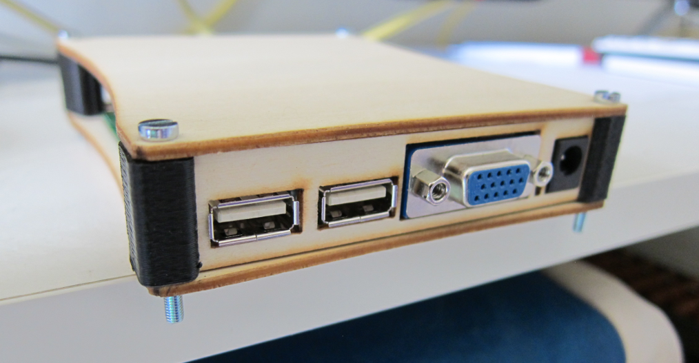
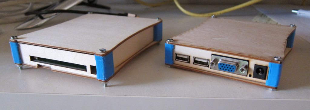
The 1.7 PCB was finalised last month: this is a very quick update to show a photo of the new laser-cut and 3D-printed corners for the first revision casework. It's not "Designed For Manufacture" so is a bit fiddly to assemble. Some improvements will be attempted but time is moving on so if nothing else the casework will go out as a kit.
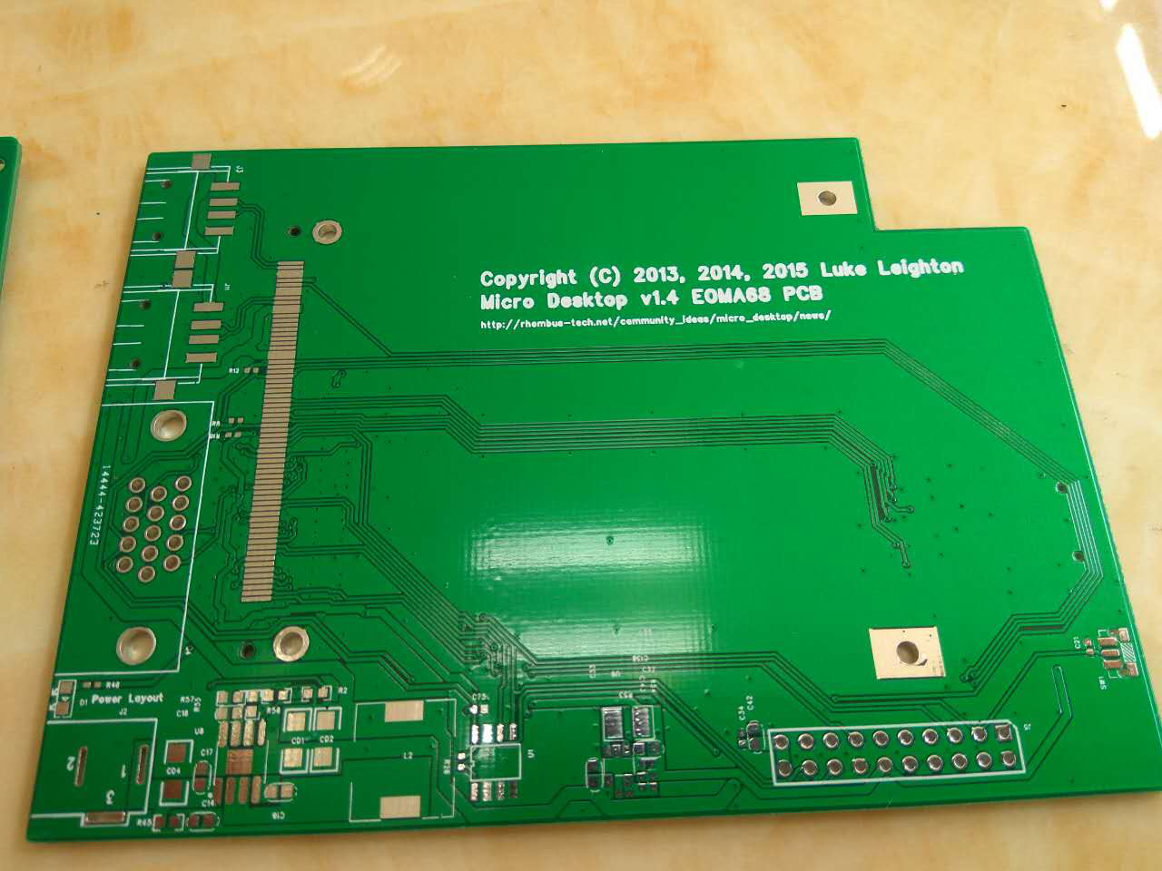
13 Oct 2016: EOMA68 Micro-desktop Revision 1.4 PCBs
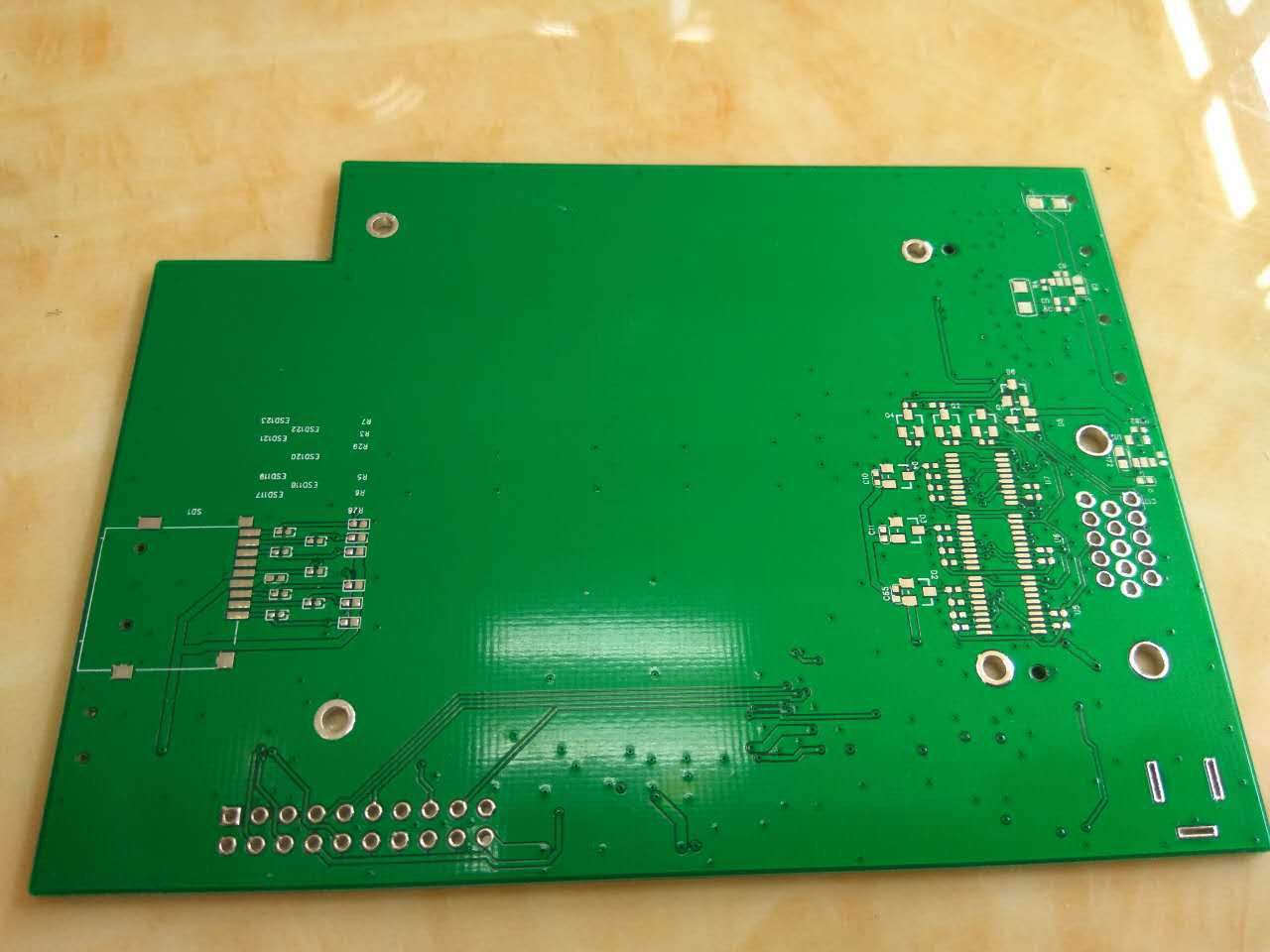
First pictures of the EOMA68 Micro-Desktop v1.4 PCBs, mike is very very busy but had time to kindly take these. As mentioned on the EOMA68-A20 page, these will be populated shortly and testing can be done, in Shenzen.
19 Jun 2016: Parabola ARM GNU/Linux OS running XFCE4 EOMA68-A20
This video demonstrates Parabola ARM GNU/Linux on an EOMA68-A20 CPU Card successfully running XFCE4, LibreOffice, and a webkit-based web browser. The entire source code right down to the boot process is entirely libre i.e. every single line of source code is available for inspection and review: there are no unknown pieces of firmware which could be doing something that you cannot verify, or were not consulted as to whether it should be doing what it is doing.
17 Jun 2016: Parabola ARM GNU/Linux OS first boot on EOMA68-A20
First boot of Parabola ARM GNU/Linux on an EOMA68-A20 CPU Card has been successful. This is part of the upcoming crowd-funding campaign that is due to launch very soon at Crowdsupply.
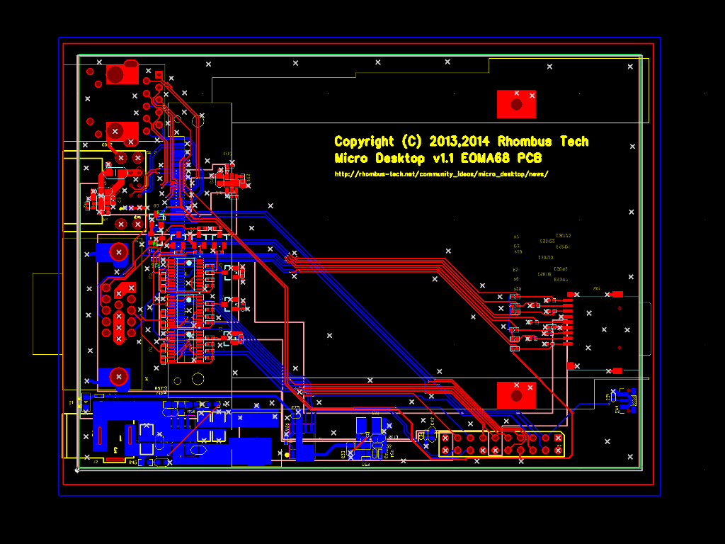
10 Nov 2014: Revision 1.1 screen-shot
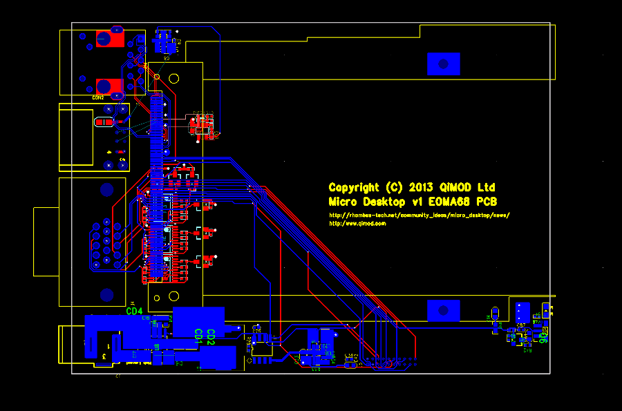
The modifications for the Revision 1.1 Micro Desktop have been completed, and the opportunity taken to make a more beautiful layout. Although it sounds strange to do that, it is often the case that a more artistic PCB design is one which is more likely to not have problems!
27 Oct 2014: Status of Interfaces with EOMA68-A20 CPU Card
Working with the Revision 1.0 of the Micro-Desktop for the past five days has the following results. The changes needed have been implemented.
-
Ethernet is functional.
Lower USB2 port is functional.
All power regulators (DCIN, USB 5.0V, 3.3V and EOMA68 5.0V)
are confirmed functional.
Power / Reset button is functional.
Power LED is functional.
Micro-SD (on the Micro Desktop PCB) has been confirmed functional as
a 2nd SD Card slot, including SD-Card detection
(A20 script.fex includes the GPIO line for SD card detect).
VGA was rotated 180 degrees. A set of 10 wires was used to confirm
that the VGA circuit itself is functional.
The VGA protection diodes were mirror-imaged. The PCB-schematic part
has been corrected.
The 2nd USB2 on the EOMA68-A20 CPU Card was inverted. The Micro
Desktop PCB itself is fine.
TOP and BOTTOM had not been flood-filled. In the re-layout this has
now been done.
The 1.27mm 20-pin header was just far too small. It has been replaced
with a 2.54mm 20-pin standard header.
The power enabling circuit was too complex (or too simple, depending
on perspective). An attempt was made to detect clashes between 5V in
and USB-OTG power. However the circuit implemented would result in
continous power-cycling, so has been simplified to rely on the SY6280
thermal cut-off protection, instead.
The EDID EEPROM on the LG VGA Monitor tested had no proper addressing
set. It therefore occupied all I2C addresses from 0x50 through to
0x53, taking up the space occupied by the EOMA68 I2C EEPROM at 0x51.
The EOMA68 I2C lines therefore cannot be used for VGA EDID data,
and must be separate.
With two GPIOs being freed through the power management simplification
these were allocated instead for a bit-banging I2C driver.
All in all it looks like quite a lot however it is actually a very simple board - surprisingly with 100 components - so the above corrections have been done on-the-go and have taken only around a day to complete.
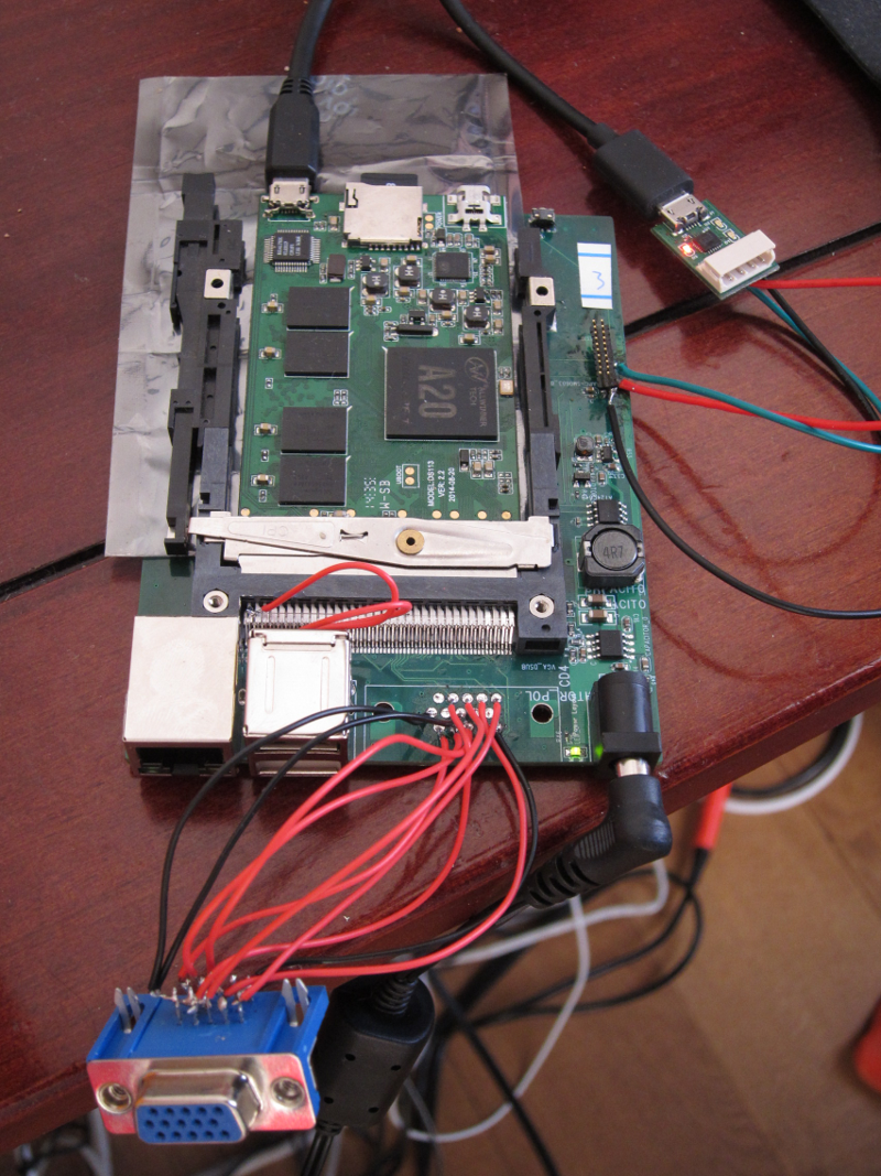
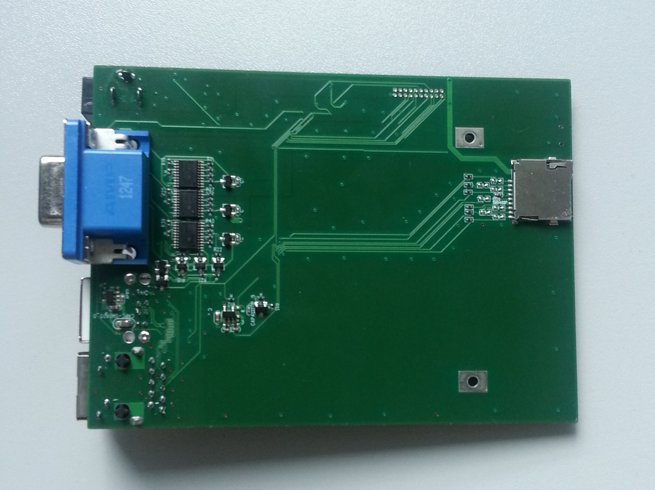
Obligatory photo - the rotated (working) VGA connector can be seen dangling down. Power supply is an off-the-shelf 12.0V however anything from 7V to 21V works fine. Soldered to the 20-pin header is a USB-to-RS232 converter for serial console and early boot access. Wires can be seen behind the 2-port USB socket, in an effort to swap D- with D+. In the EOMA68-A20 CPU Card can be seen the Micro-SD slot which contains a Debian GNU/Linux 7.0 root filesystem. Next to that is a USB-OTG cable which, half way along, has had its 5.0V line cut. This modification to a standard USB-OTG cable has proved invaluable. The CPU Card shown is one with 2GB of RAM.
24 Oct 2014: Interfaces confirmed working with EOMA68-A20 CPU Card
The Micro-Desktop board's have been confirmed as having 5V power, 3.3V power, Ethernet and VGA operational. One (lower) USB2 is operational sporadically and the other is producing errors: there are however no Ground Planes and the USB2 connector parts installed in these prototypes are not exactly the same ones as required for production.
VGA turns out not to be mirror-imaged but actually 180 degree rotated. A VGA connector has been de-soldered and wires used to run to the connector. This has resulted in a successful test at both 800x600 and 1024x768 VGA resolutions. Video and pictures will be provided later.
14 Oct 2014: First prototype partially tested with EOMA68-IC1t
Thanks to ICube Corp the 5V power and the Micro-SD card slot were tested and confirmed working by way of a successful board bring-up with the EOMA68-IC1t prototype. One other minor error was also found in the process, which was corrected in the Micro-Desktop prototypes: the BAT54S shottky protection diodes were found to be mirror-imaged and needed to be placed face-down. The boards have been shipped and will be tested fully with the EOMA68-A20, later this week.
11 Oct 2014: Routing rework
From the photographs yesterday it was noted that flood-fill on both TOP and BOTTOM layers was missing! Whilst connectivity of the first assembled prototypes should be fine, and there is a fully-flooded GND plane, it is highly desirable to have both TOP and BOTTOM unused areas flooded and linked to GND as well. Along with some minor re-routing, addition of plane connection vias and of course the mirror-imaging of the VGA connector so that it can go on TOP, a preliminary rework has been done pending verification when the first prototypes arrive next week.
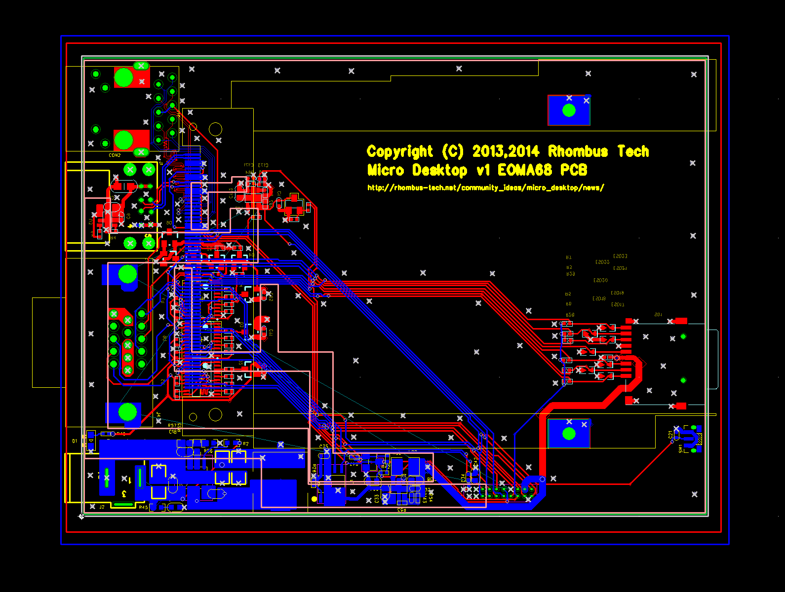
10 Oct 2014: First prototype
First prototypes are back from assembly. They are still currently in Hong Kong, and are to be shipped back for testing shortly. First most obvious mistake is clear: the VGA connector PCB layout was mirror-imaged! This is easily corrected but requires around $600 for reworking. The remaining functionality will be fully tested before that happens, but these boards will be sufficient to go ahead with the crowdfunding campaign.
Also, note the addition of a Micro-SD card slot, since SD/MMC was added to the latest EOMA-68 specification it was considered a good idea to take advantage of that in this very small board. Micro-SD was used instead of full-sized SD because the part is already used on the EOMA68-A20 CPU Card. On that board the Micro-SD circuit is a known quantity, tested and proven already, and the supplier details are already known. It was considered expedient to not redesign the circuit or find other untested parts.
29 May 2014: First revision routing
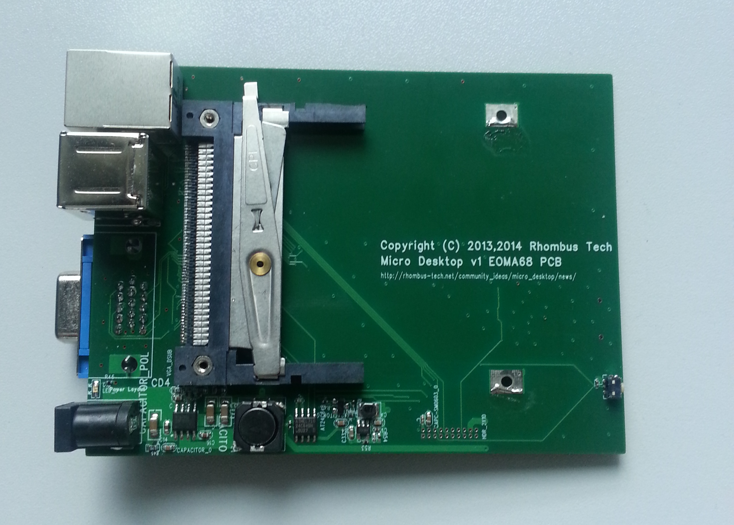
The Micro Desktop PC is a cut-down version of the Mini Desktop and the PCB size is around 4.5 x 3.0 in with USB, Ethernet and VGA connectors overhanging the edge of the PCB by about another 0.25in.
Connectors are arranged as follows: Top left is Ethernet, then downwards comes one dual-stacked USB2 connectors and the VGA port, followed by a a standard 5.5mm power jack (2.1mm centre pin), Bottom right is the reset switch and along the bottom edge is a 20-pin Expansion Header (1.27mm). All connectors are TOP side, with very few components underneath.
In essence this is a very simple board. RGB/TTL conversion to VGA has been kept to an absolute minimum by having buffer ICs straddle the EOMA68 RGB/TTL outputs within a few mm. All other high-speed signals are differential pairs. The design is nearly 100% complete: the 3.3v, 5.0v and USB power planes need to be done and it is ready to go.