Micro Engineering Board
The Micro-Engineering Board is very simple: it is almost nothing but through-connectors (plus an identifying I2C EEPROM for EOMA-68 compliance). The PCB layout has been completed (as of 2013jun05) and a first prototype will be assembled very shortly.
It is suitable as a test bench, as well as being suitable for experimental purposes as well as having the potential to turn an EOMA-68 CPU Card into a very simple Desktop PC. An Allwinner A10/A20 CPU Card in combination with this board would have SATA, Ethernet, USB Host, HDMI, SD/MMC, USB-OTG and take 5V power, as well as having internal access to 8 pins of GPIO and an I2C interface.
IMPORTANT MODIFICATIONS TO 1ST REVISION
- remove R2 THIS IS REALLY IMPORTANT FOR THE NEWER EOMA68-A20 BOARDS
- short out D1 and MAKE SURE YOU USE EXACTLY 5.0V power
- put a wire between pin 1 and pin 11 on the underside of the PCB, on J4.
Features
- Ethernet RJ45 connector with built-in transformer
- SATA connector
- 5V power connector (with capacitor and zener diode protection)
- upright USB connector
- 44-pin DIL header with remaining EOMA-68 pins (RGB/TTL, GPIO and I2C)
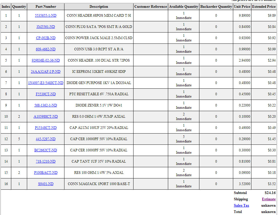
All parts are orderable from Digikey and are through-hole (pins) so can be hand-assembled. The gerber files can be made available if anyone wishes to print a PCB.
Pinouts
These are the pinouts for the 44-pin connector:
- Pin 1 GND
- Pin 2 LCD R0
- Pin 3 LCD R1
- Pin 4 LCD R2
- Pin 5 LCD R3
- Pin 6 LCD R4
- Pin 7 LCD R5
- Pin 8 LCD R6
- Pin 9 LCD R7
- Pin 10 LCD G0
- Pin 11 LCD G1
- Pin 12 LCD G2
- Pin 13 LCD G3
- Pin 14 LCD G4
- Pin 15 LCD G5
- Pin 16 LCD G6
- Pin 17 LCD G7
- Pin 18 LCD B0
- Pin 19 LCD B1
- Pin 20 LCD B2
- Pin 21 LCD B3
- Pin 22 LCD B4
- Pin 23 LCD B5
- Pin 24 LCD B6
- Pin 25 LCD B7
- Pin 26 LCD CLK
- Pin 27 LCD VSYNC
- Pin 28 LCD HSYNC
- Pin 29 LCD EN
- Pin 30 I2C-SCL
- Pin 31 I2C-SDA
- Pin 32 GPIO 0
- Pin 33 GPIO 1
- Pin 34 GPIO 2
- Pin 35 GPIO 3
- Pin 36 GPIO 4
- Pin 37 GPIO 5
- Pin 38 GPIO 6
- Pin 39 GPIO 7
- Pin 40 RES1
- Pin 41 UART_TX
- Pin 42 UART_RX
- Pin 43 GND
- Pin 44 +5V
Case available
A case is available for the MEB, pictures and example here: http://www.gplsquared.com/eoma_boot/eoma_boot.html
Pictures
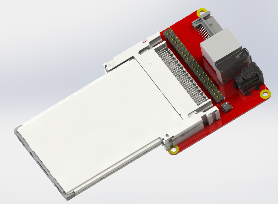
These are very early 3D CAD/CAM prototypes, done prior to the PCB layout (which is now slightly different)

This image shows the early CAD/CAM of a Micro Engineering Board with an EOMA-68 CPU Card:
Here's the BOM on mouser.com:
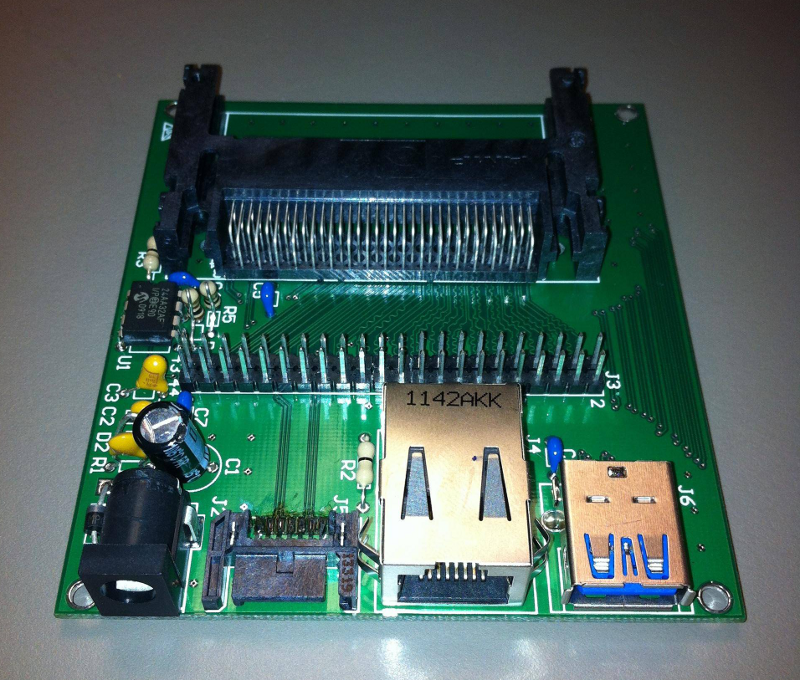
Finished item! Many thanks to Firemoth Industries and to Leo for the work here. It's amazing to see this coming together.
Picture of a suitable MEB case, at gplsquared:
