13 Nov 2013: First revision connector placement
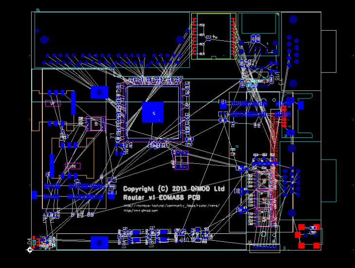
Connector and approximate component placement has been arranged in a double-sided arrangement. This allows the PCB size to be kept to around 115 x 95mm (4.5 x 3.6in) which is around the same size as the Flying Squirrel PCB. Connectors round the top edge (BOTTOM side) are the 4-port Gigabit Ethernet, then a Gigabit Ethernet transformer, then 2x USB2 and RS232. Down the right side (BOTTOM of PCB) is RS232, SATA, VGA and Power. Behind the Power connector is an 8-pin Extension connector which has I2C, 5V, GND and 4 pins of EOMA-68 GPIO. In the centre is the EOMA68 connector (still on BOTTOM) and the Power Switch is in the bottom left corner. On TOP are the two MiniPCIe USB holders for WIFI and 3G USB-based full-sized MiniPCIe cards.
Almost all discrete components are on TOP because there is very little available space on the BOTTOM side due to all the connectors. There actually aren't that many components left to put on: there is the LEDs for the 4-port Ethernet and a 5V regulator to be sourced which can provide enough power for the RTL8366 as well as the EOMA68 CPU Card, as well as power four USB ports. The 4 USB ports are up to 10 watt on their own (!), the RTL8366 is 3 watts and the CPU Card could potentially be up to 4. To be honest a potential total of 20 watts is of some concern!