01 July 2015: First 3D print of full-sized parts
The first attempt to 3D print a full-sized version of the 15.6in laptop is underway. The prior 3D prints were all of a dummy "test" variant which allowed for elimination of many potential errors without needing to waste large amounts of plastic in the process, however modifications had to be made since then, and already, even though only 4 full-sized parts have been printed, adjustments have already had to be made.
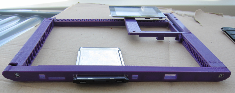
Despite this, it is still exciting to see how the sample keyboard and touch-LCD fit into place: after 6 months of CAD/CAM work including one abortive design the project is beginning to see genuine visible results. The first image shows how the keyboard and touchpanel fit in place. The second shows how the mid strut supports the touch panel, as well as show the internal cross-hatching that increases the structural strength of the mid strut as well as reduce torquing. The third image shows the connectors: from left to right there is the Stereo Headphone/Mic jack, on-board Micro-SD, CPU Card slot and one full-sized USB. DC Jack and Power / Reset button will be on the opposite side.
As this is the first 3D print which involves the actual parts that are
to be used, mistakes in measuring the parts (keyboard, touchpanel) have
already been detected. The touchpanel measurements were easily corrected
from one of the (many) aborted attempts to print the touchpanel tray
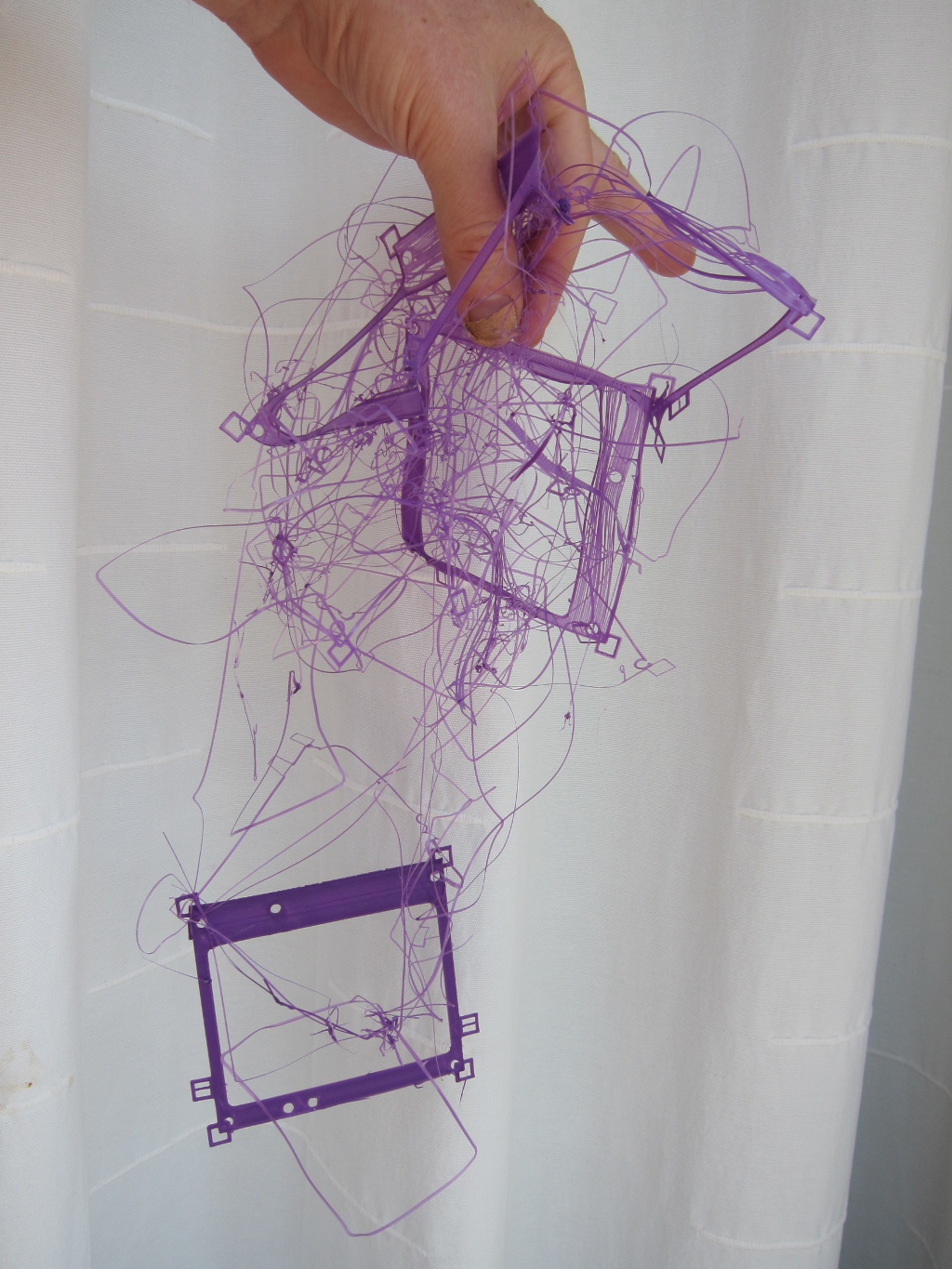
(see spaghetti below containing over
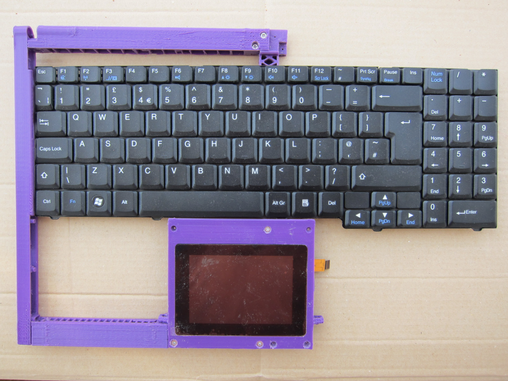
This leaves a gap above the keyboard of exactly 79mm that needs to be filled in! How this is to be resolved is yet to be decided, as the cross-braces which interlock at the corner of the touchpanel (two for the keyboard, one for PCB1 and one for the battery) have already been designed. Changes here (pushing the keyboard back) therefore have some significant ramifications including requiring PCB1 to be redesigned as well. The most likely candidate change therefore is to fill in the back 79mm above the keyboard, which has the advantage that it is possible to consider putting in some LEDs above the Function Key row.

Top view of the casework showing the Touch/LCD in place as well as the keyboard. It is clear from this picture that there is an extra 79mm above the keyboard.

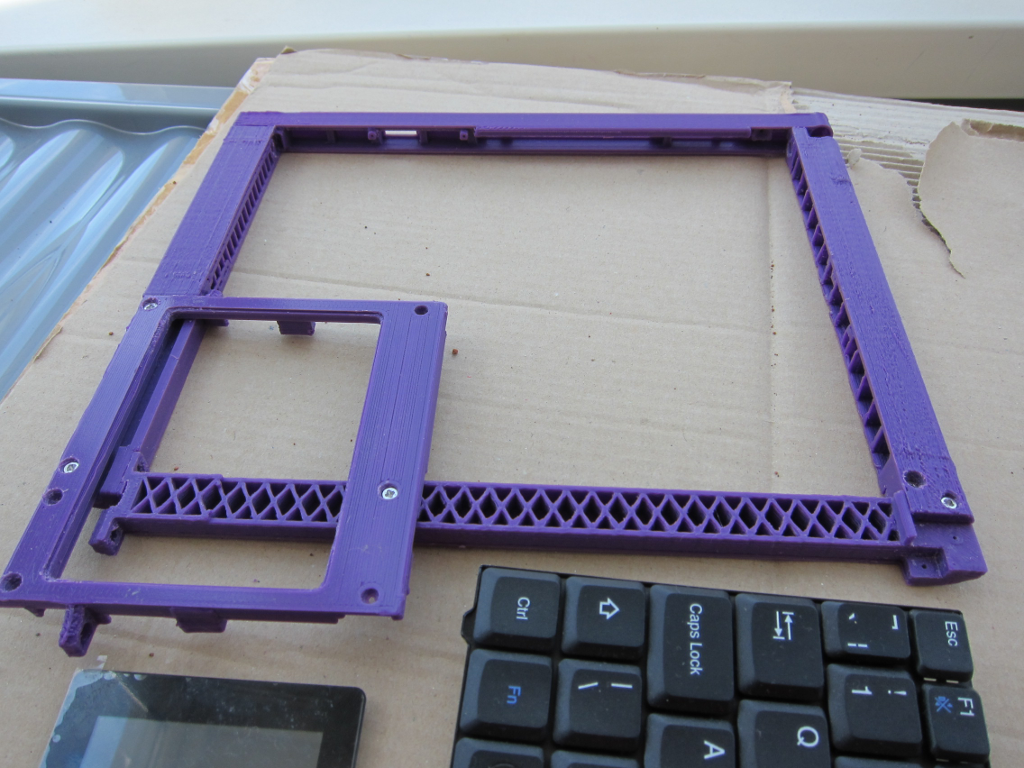
Image showing the base mid strut. There is a cut-out in the strut, below where the touchpanel/LCD sits. This is for PCB2, which will fit in a C-shape to reach around and out beyond the touchpanel holder, for the keyboard FPC to fit into as well. PCB2 will have a Micro-Controller that will manage the touchpanel via I2C, the 480x272 LCD via SPI, operate a keyboard matrix scan to detect key presses, and convert the touchpanel and keyboard input into USB-HID events.

Nine attempts to print the touchpanel tray. Despite the small squares at the corners (which have been found to be necessary to keep the PLA sticking down to the heated glass) there was something extra-weird about this particular shape that meant that it just absolutely refused to stick.
