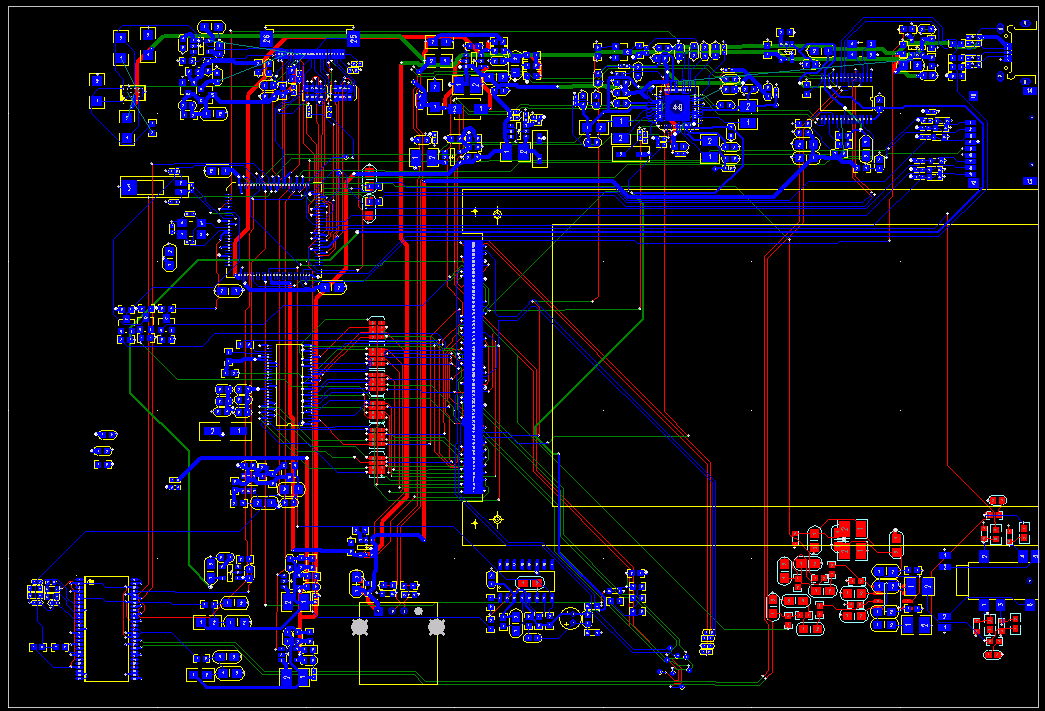
8 Jan 2013: 1st attempt at a PCB layout
As a first approximation, this is an inexperienced attempt to create a layout for the Flying Squirrel. Quite a lot of difficulty has been experienced convincing Chinese ODMs to stop trying to 'recommend Android, A10, A13, "we can do it this way much better, you don't wanna do that Old-School stuff", where's the HDMI interface, surely this isn't an actual tablet, it's got no processor, what's it doing with LVDS, did you actually want a screen, it must be some sort of voodoo magic industrial device, therefore we must charge you more money'. Eventually a decent industrial-style designer was found who wasn't fazed by the sheer oddness of putting in an STM32F, and who really liked the EOMA-68 concept. I like Franson.
The size of this very very early PCB layout is 120mm x 175mm. The size being aimed for is around 117mm x 160mm. Also, the PCB is being designed so that as a Tablet, all connectors are on the right-hand edge (another USB-OTG, another Micro-SD, Headphones and Power), and, also, for future products and also for engineering purposes, an extra USB2, an Ethernet RJ45 and an eSATA can be added. Bottom left is a temporary component (that happens to have 54 pins), which will be replaced with a PCB decal for a JAE Mini PCIe socket shortly.