30 Dec 2014: Third revision 3D printed prototype casework
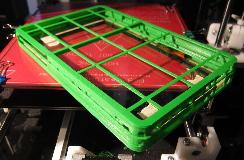
Finally a version that snaps together and does not require significant modification, only cleaning up where the printer has left trails. A better printer may produce much better results here. Shown below are the two parts that snap together (no screws required), trapping the touch panel inside. Once on, however, it does not come apart so is not being assembled until the PCB is available and confirmed working.
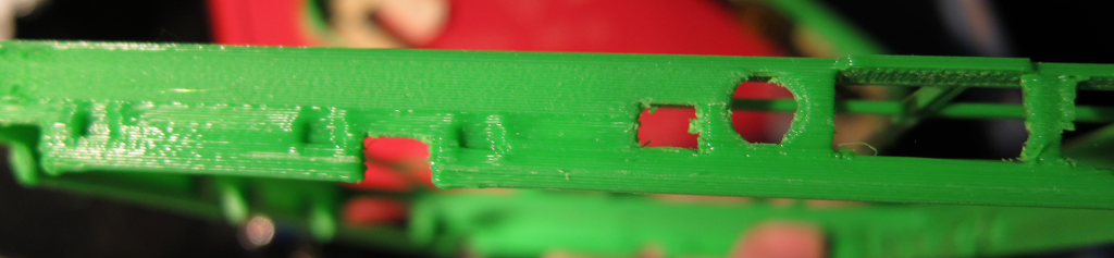
Detail below shows how the case stays together. On the inner part are indentations (usually two either side of a cut-out), and there is one indentation in each corner. On the inside of the exterior part is a clip with two bumps either side. The bumps fit into the indentations and the clips capture the inner case and ensure that it remains in contact with the exterior.
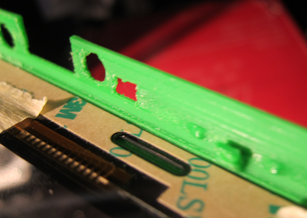
Finally it can be seen where the CPU Card goes:
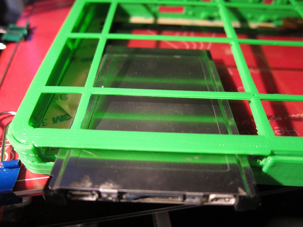
Challenges here have been that, firstly, when fitting the touch panel, the accuracy of the printer came into play, with the gcode often sending the head into the exact same corner a signifncant build-up of waste extrusion would occur right where the panel was supposed to go. Secondly, it turned out that the capture clips were in the way, preventing the panel from going into its recess at all! Two capture clips were therefore removed from near the corners on one of the longer edges. The touch panel can then be slotted into the opposite (long) edge, underneath the capture clips, then the remaining three sides bent slightly outwards at their middle points to allow the touch panel to drop in. With the plastic being so thin this is perfectly feasible. Surprisingly the touch panel provides a significant degree of rigidity to the whole assembly, although one corner may be lifted off by 5mm! In all this has been extremely lucky: the outer dimensions are around 125mm x 196mm which is just on the edge of being printable on a standard 200mm x 200mm mendel90.