01 Dec 2015: Libre Laptop PCB 1 LCD semi-operational
After several frustrating weeks the LP156WH4-TLN2 LCD finally sprang into life. Four LVDS ICs, one A20 CPU Card, three LVDS cables and one 15in LCD were destroyed in the process of getting to this point! The chain involved correctly configuring the script.fex file for the Allwinner A20 processor; ensuring that the LVDS IC was soldered correctly and operational; ensuring that the connector was soldered down correctly (this had to be checked twice); creating a reverse-cable (3 days) due to the connector being the wrong orientation; working out the LCD parameters... any one of these things in the chain could cause the LCD to be non-operational, with no easy way to ascertain the potential fault.
With the LCD being activated, finally, at least it is now possible to experiment with script.fex settings and possibly with linux kernel modifications, to see if the display quality can be improved. So this is huge progress, as apart from the Audio Amp circuits (yet to be debugged), everything else is working: USB Hub, CM108AH, MicroSD, and the 3 full-sized USB Ports.
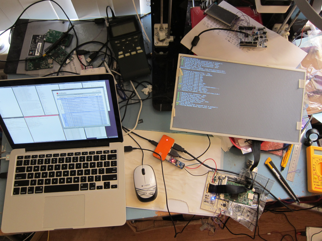
Here is a photograph of the test setup. Top left corner is the spare EOMA68-A20 CPU Cards. Maplin's $75 70mhz Digital Scope next to it. Top right is an STM32F072 Nucleo test board with the Yunlea 480x272 SPI LCD still attached. Bottom left is the development laptop: on-screen can be seen the LP156WH4-TLN2 datasheet, and the tiny xterm to its left is the RS232 console output. Bottom middle is the 4-port USB Hub with power via USB to PCB1, a USB-UART dongle for RS232 console. 2nd Power is provided to the USB-OTG port of the EOMA68-A20 CPU Card via the laptop. In the bottom left corner is PCB1 with an EOMA68-A20 CPU Card, with the hand-assembled LVDS cable up to the LCD. Finally, just dangling off the edge of the desk, is PCB2, with the STM32F072 Embedded Controller.
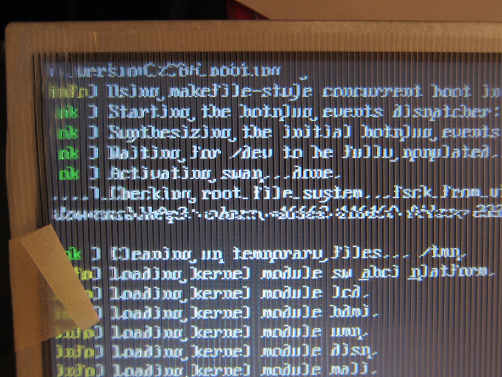
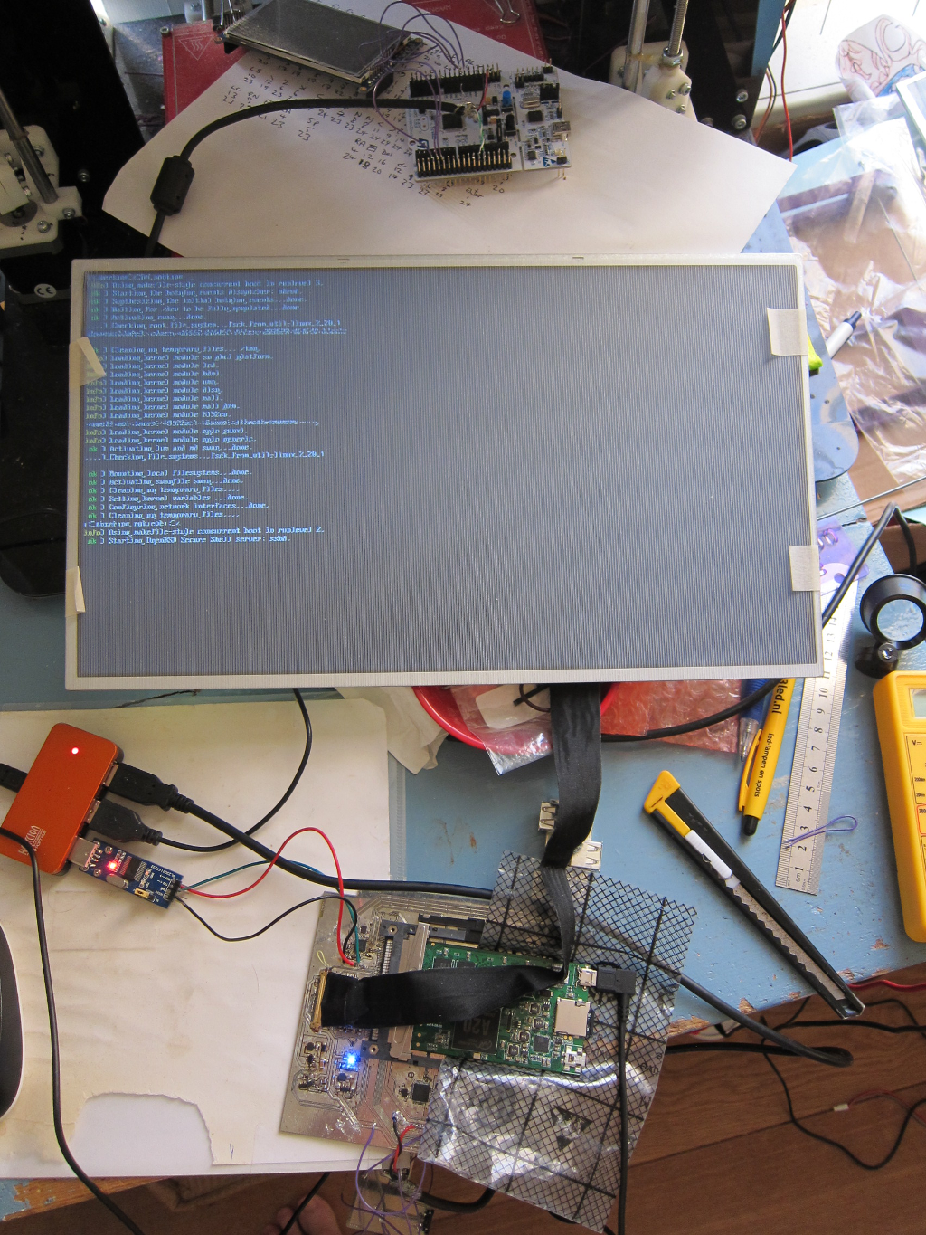
Here is a screenshot showing the LCD more clearly. The standard Debian boot process can be seen.
Here is a more detailed screenshot of the "oddness" that's occurring. Despite several revised changes to the script.fex file, nothing seems to get rid of the artefacts, which is very strange. E.M. noise is therefore suspected, so it will be necessary to do a 2nd revision of the PCB to find out if that's the case. A 2nd revision is necessary anyway, as the LCD backlight boost circuit needs redesigning, and there are some other minor changes needed as well.