04 June 2015: Supporting PCB1
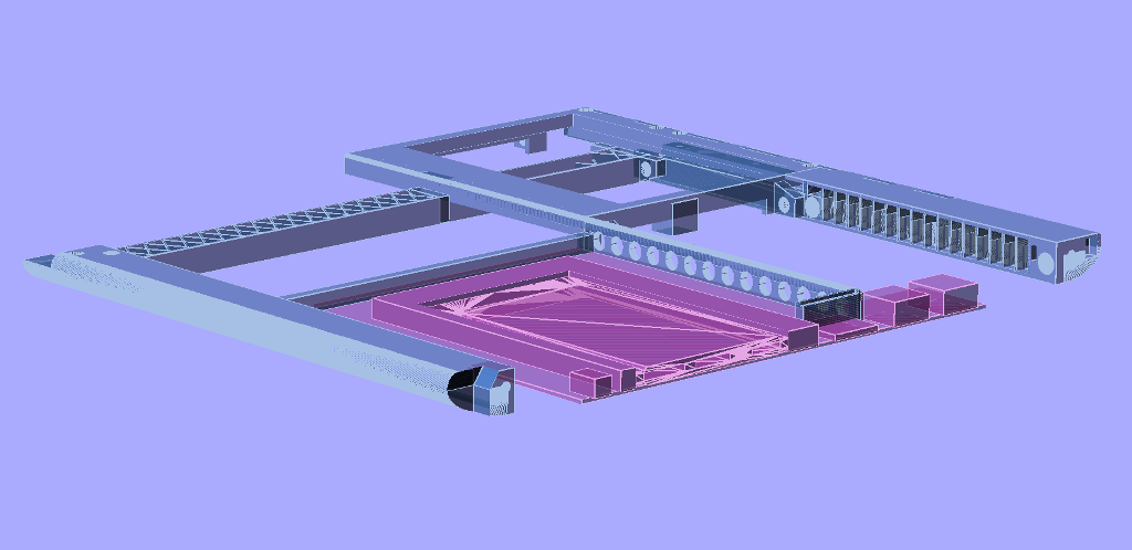
This is tricky. In the centre of the image below is a structural weak spot where several pieces hang together. The touchpanel holder (top of picture) is able to "wobble" about the middle strut (the piece with the structural X-hatching) in a see-saw motion. The far inside end of PCB1 (in magenta) is also able to move up and down, as is the front keyboard tray support (with the oval holes).
So the idea is to put in an inner strut (which can be seen at the back of PCB1), and screw it to the corner of the touchpanel part. Then the keyboard tray support part can lock into that. The PCB can then be screwed (or 3M double-sided taped) to the strut, and thus all the pieces help support each other.
There are so many mechanical details in this design! In many ways, designers that create one-piece boxes have a much easier time: create a box with curves, put in some holes, put in some regular support struts across the floor that stop it from bending, and that's it. Unfortunately, as it would require 50 hours 3D printing (which could fail at any time), and would also require a very large $1,500 to $2,000 3D printer with an enormous print area, a single-piece design for this project is simply not practical. Therefore, a multi-piece design is the answer, with the added benefits that single pieces may be replaced; they may be re-printed if there is an error (without discarding all other pieces); and that a very large amount of the design may use renewable materials (bamboo laminate panels).