26 Sep 2015: Libre Laptop PCB 1 component population update
Populating PCB1 with components is progressing slowly and carefully: the T870A IRDA soldering station is crude, functional and effective. In the photo below can be seen the PCB, the camera and, just above that, a head-mounted magnifying glass... on a head. With some of the components being 0402 it is near flat-out impossible to place let alone hand-solder components: the magnifying glass and the T870A have very effectively taken care of that.
Confirmed working circuits so far:
-
LCD backlight step-up converter (output measured at 17V with no load)
LCD digital 3.3v supply circuit: this contained a mistake (MOSFET
rotated 120 degrees), which can be seen in the bottom right corner,
one MOSFET clearly isn't straight.
SY8008B DC-DC converter 3.3v supply. A mistake was made in selecting
a SY8060, which indicates "Power Good", whereas what was needed is
the SY8008B which is told "Power On / Off" as an input. A spare SY8008B
was found.
3.3v LED. The first one that was placed on the board, with the T870A,
melted completely beyond useability. The second one was hand-soldered.
CMedia CM108AH USB Audio! This was the latest addition, today. The
12mhz XTAL was on the wrong pad size: some assessment showed that it
was likely a 4225 layout not a 3225 (3.2 x 2.5mm) layout. Careful
shaving of the GND plane between the XIN and XOUT tracks made it
possible to lay the SMD 3225 XTAL across the available space without
shorting (the second time, at least)
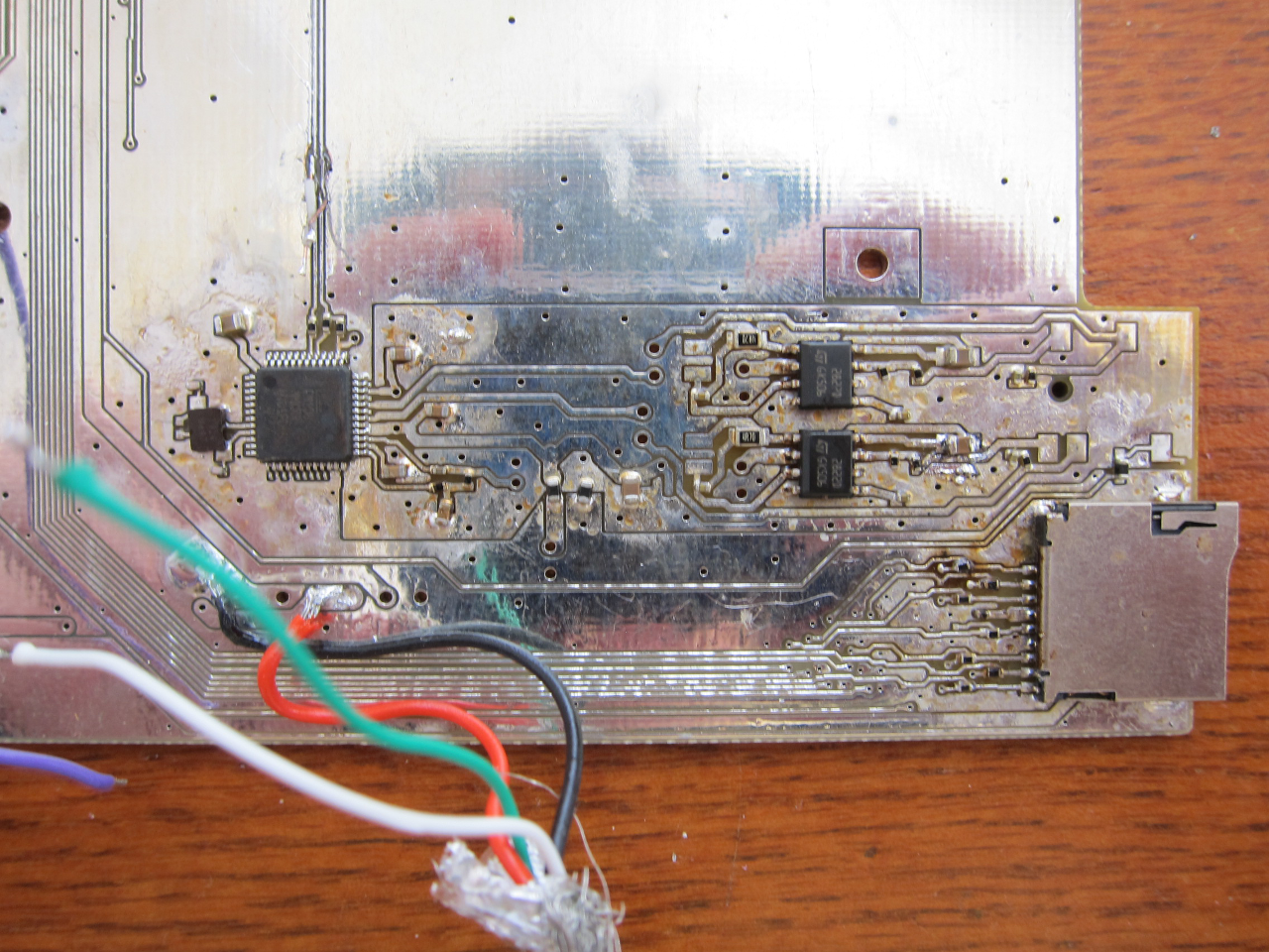
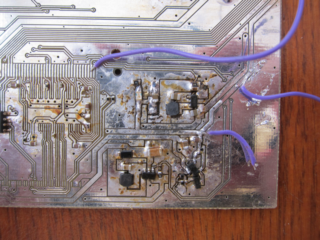
Here you can see the dog's dinner mess which comprises the Power Conversion circuitry. At the top is the SY8008B. The layout is not perfect, and will need to be redone. Also, there was a short on the output (on the two MOSFETs) which was very confusing: the output was reading 0.7v instead of 3.3v and there was no immediate short. A more experienced electronics engineer would have immediately suspected the short to be the other side of the 3904 transistor: this had to be deduced, hence the reason why the SY8008B support components had to be removed (several times).
In the bottom right corner is the LCD digital 3.3v supply circuit which can be switched on and off via GPIO, so as to save power. Hence the 3904 transistor which enables/disables the MOSFET just above it. However the circuit definition of the MOSFET had all gates rotated. This took several hours to carefully diagnose and correct, and fortunately it turns out that yes it is possible to turn a SOT23 MOSFET round through 120 degrees and it will just fit across the pads.
In the bottom left is the SY7201 (a Richtek RT9293 will do as well) which is a step-up converter that can switch up to 2A - a heck of a lot for an SOT23-5. Fortunately only 3.5 watts is needed for the AUO Optronics LCD backlight. The layout here unfortunately isn't ideal, however an app note wasn't available at the time. The copper on the high-frequency output from Pin 1 (bottom left pin) should have the smallest possible space, to avoid EMF, and as can be seen it's pretty large. This will need a redesign.
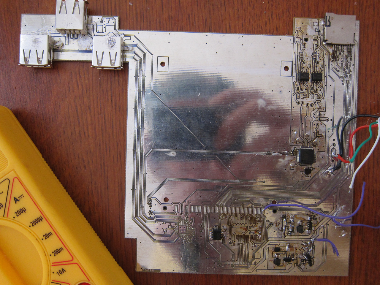
The CM108AH USB Audio IC (left here) was taken from a working dongle as the parts from Hong Kong haven't arrived yet. Just above it on the USB tracks can be made out two flying leads: these were used to test whether the CM108AH appeared on the USB bus (it did!). Initially the device didn't work but this was found to be because the 3.3v internal regulator (top right pin, top row) wasn't soldered down properly. Once that was corrected it functioned perfectly. The crystal, as mentioned above, was a pain. The pads can clearly be seen to be the wrong size. Why this wasn't spotted before PCB printing is a mystery. Turns out that 12pF capacitors and no 1M Ohm resistor do the job: the CM108AH is capable of driving those to resonance even though the Reference Circuit says 20pF. Rule of computing (and electronics): if it works: don't change it!
To the right is the pair of TDA2822 Audio amplifiers. The entire area here is on its own separate plane (above and below), isolated with two 1.2A ferrite beads (visible 1/4 of the way along the bottom of the analog area). This part hasn't yet been tested, but will be shortly. It has also been redesigned slightly, because some of the component sizes were judged to be wrong on careful inspection and consideration. The circuit should be perfectly functional for a prototype however.
Lastly we have the push-push Micro-SD which is extremely common in China but is so terrifyingly generic that nobody even has a proper name for it, not even amongst the many different suppliers. This one was lifted (thanks to the T870A) from another PCB in about 30 seconds. Just to the right is a set of termination resistors - all 0402. Why exactly 4mm x 2mm resistors and capacitors were chosen for this board, when it is being hand-assembled, will have to remain one of those puzzling unanswerable questions.